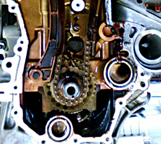
Crankshaft Slot
The most important sensors of any engine, the crankshaft and camshaft position sensors are integral to the functionality of the distributor and ignition timing.
CRANKSHAFT POSITION SENSOR

The crankshaft position sensor monitors as a multifunctional sensor used to set ignition timing, detect engine RPM, precise position of the engine crankshaft and relative engine speed. This sensor negates the need for manual distributor timing. The camshaft position sensor is used to determine which cylinder is firing to synchronize the fuel injector and coil firing sequence.
Typically, the key wears the keyway slot in the crankshaft nose. Worn keyways are not repairable. In other cases, the pulley bolt will fail to stay tightly screwed to the front of the crankshaft. Insufficient tightening torque upon assembly is an obvious cause. No batteries, no plug-in. You have a hand generator that makes the 'juice' and controls the speed! And it all fits in its.
Read more : Car Sensors Types , Function of Vehicle Sensor
In some cars, the sensor is installed close to the main pulley (harmonic balancer) like in this Ford in the photo. In other cars, the sensor could be installed at the transmission bell housing, or in the engine cylinder block, as in the photo below. In the technical literature, the crankshaft position sensor is abbreviated to CKP.
FUNCTIONS
1. Sensing
If you look at the crankshaft, you will find a powerful magnet next to it. You will also find that there are steel pins or pegs arranged at regular intervals around the crankshaft.
This magnet constantly radiates a magnetic field that is steady. As the engine starts and the crankshaft spins the steel pins around the shaft rotate around this field. This causes fluctuation in the field, thus producing an AC (alternating current) signal. This further signals the engine management unit (engine computer) to decipher the speed of rotation. In turn, the EMU is able to calculate the position and the pace of the camshaft to further optimize fuel injection and ignition.
2. Adjustments
The way modern cars are, we must learn one thing. The engines will give us an efficient performance only if the internal parts are moving at a particular recommended speed. It is only once the crankshaft position sensor senses the rotation of the crankshaft inside the engine that the on-board can make use of the information that the sensor sends to it. This is when the computer will make small adjustments/fine-tunings in to the engine to increase its efficiency.
Consider the cases when you are moving full-throttle. The constant throttle in modes like cruise mode or sports mode, the computer needs to make these fine adjustments to the engine in order to change the speed. The computer will ensure that it constantly checks the rotational speed of the crankshaft, compares it to the ideal range, and make speed adjustments accordingly. This adjustment can be in terms of both increasing and decreasing the speed.
TYPES OF SENSORS

There are three main types of sensor:
1. Inductive:
Uses a magnet to pick up a signal from the engine cranking. Either mounted in the block of the engine, near the fly wheel or close to the crankshaft itself. It picks up notches on a spinning disk, reluctor wheel or the crankshaft. When each notch passes, it causes a change in the magnetic field, sending an alternating current signal to the ECU.
2. Hall Effect:
This type is mounted in the same places as the inductive sensor and responds to the same notches. Though instead of an analogue AC signal it creates a digital signal. Either on or off, as the notches pass the sensor.
3. AC output sensor
Crankshaft Stopper
AC output sensor is different from the others in that the output is an AC voltage signal. The onboard controller generates very high frequency (between 150 and 2500 cycles per second) to the exciter coil, which is located near the rotating disc. This disc is mounted at the end of the camshaft and there is a slot in it. When the slot passes the coil, it is excited by the mutual inductance and a signal indicating the position of the first cylinder is sent to the onboard controller. This type of sensor is used in some Vauxhall ECOTEC engines.
WORKING PRINCIPLE

The crankshaft position sensor is positioned so that teeth on the reluctor ring attached to the crankshaft pass close to the sensor tip. The reluctor ring has one or more teeth missing to provide the engine computer (PCM) with the reference point to the crankshaft position.

As the crankshaft rotates, the sensor produces a pulsed voltage signal, where each pulse corresponds to the tooth on the reluctor ring. The photo below shows the actual signal from the crankshaft position sensor with the engine idling. In this vehicle, the reluctor ring is made with two missing teeth, as you can notice on the graph.
The PCM uses the signal from the crankshaft position sensor to determine at what time to produce the spark and in which cylinder. The signal from the crankshaft position is also used to monitor if any of the cylinder’s misfires. If the signal from the sensor is missing, there will be no spark and fuel injectors won’t operate.

The two most common types are the magnetic sensors with a pick-up coil that produce A/C voltage and the Hall-effect sensors that produce a digital square wave signal as in the photo above. Modern cars use the Hall-effect sensors. A pick-up coil type sensor has a two-pin connector. The Hall-effect sensor has a three-pin connector (reference voltage, ground and signal).